How to read a high-voltage oscilloscope pattern at the spark plug
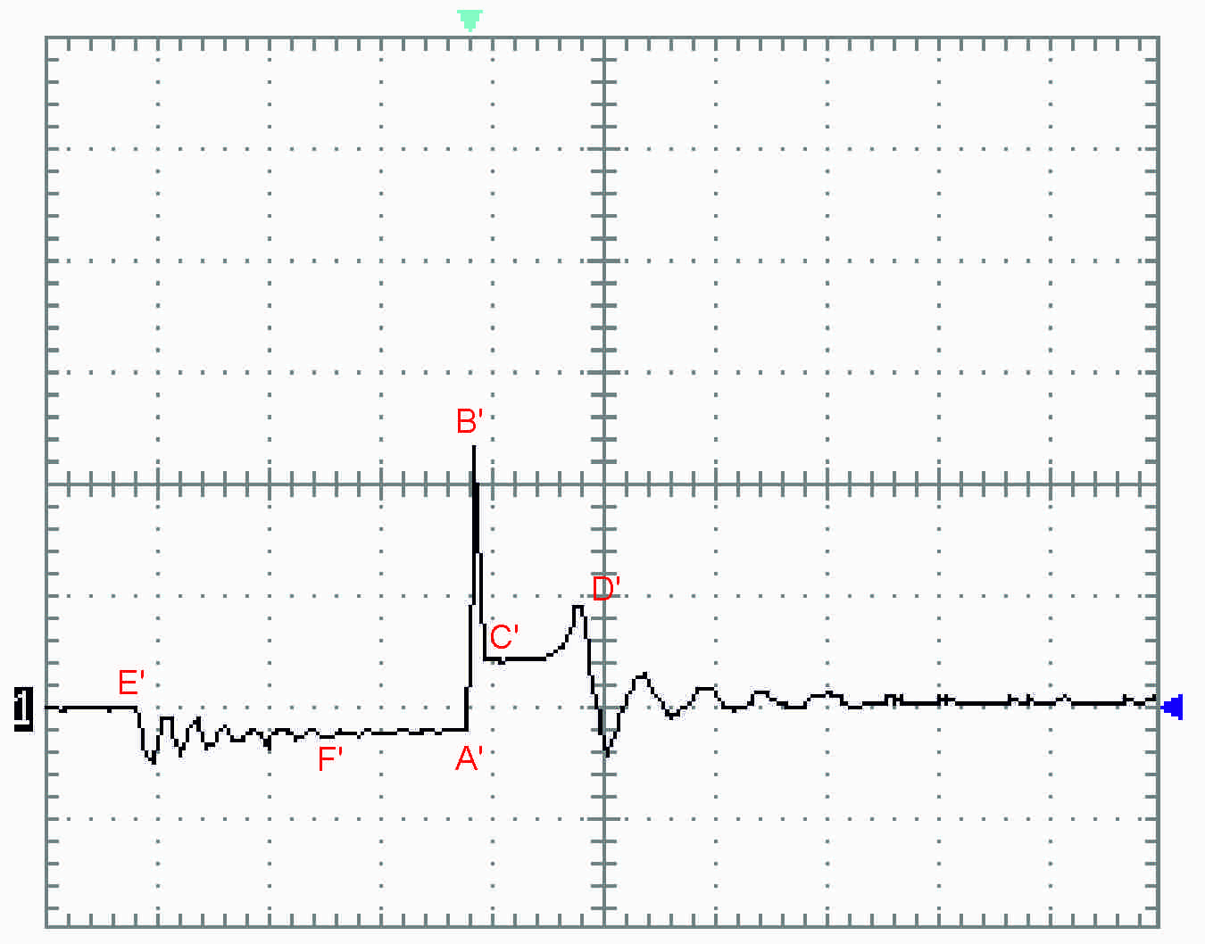
The secondary high-voltage waveform at the spark plug shows coil charging (E'–A'), voltage build-up until the spark jumps (B'), the spark line or arc phase (C'–D') and the decaying oscillations. The area under the curve between A' and D' is a measure of the spark discharge energy, and the firing voltage depends on the electrode gap, mixture composition, cylinder temperature and electrode shape.
How do you interpret oscilloscope patterns of the high voltage at the spark plug?
The graphs use the same labels as the technical literature. Labels A', B', C', D' and E' mark the characteristic points of the waveform; the "prime" sign indicates that the measurements relate to the secondary side of the coil.
The letters do not appear in alphabetical order because we present the graphs slightly differently: we start from the beginning of coil charging rather than from the beginning of the spark discharge.
The horizontal axis is time, with one division (the distance between the dotted lines) equal to 0.5 ms (milliseconds). The vertical axis shows voltage in kV (kilovolts), with one division equal to 2 kV.
Coil charging (E'–A')
Reading from the left, the first point is E' – where the coil's primary supply is switched on. This simply means connecting battery voltage to the coil's primary winding. The coil charges, and energy is stored in the magnetic field of the coil core. The charging period is when the decaying sine wave appears – on our graph this is point F', about 60% of the way between E' and A'. After that the line runs horizontally, showing that the coil is fully charged. Because a winding connected to the supply could draw a large current, causing the coil to overheat and eventually burn out, the supply circuits limit the coil current to 6 A (in most coils).
High-voltage build-up and spark formation (A'–C')
Once the coil is charged, at point A' the supply is switched off abruptly (under electronic control). At this moment the high voltage starts to build up towards value B'. The voltage reached at B' depends on three factors:
- the spark plug electrode gap,
- the composition of the air-fuel mixture in the cylinder,
- the temperature in the cylinder.
If enough energy is stored in the coil, point B' is reached and the spark starts to jump between the spark plug electrodes. At B', current also starts to flow between the electrodes, which makes the voltage drop to level C'.
Spark line and spark energy (C'–D')
From point C' the graph shows a flat section – the result of the voltage and current in the electric arc. This period lasts as long as the energy stored in the coil can sustain the arc. The area under the graph, bounded by vertical lines at A' and D' and the horizontal axis, is a measure of the spark discharge energy at the plug. Comparing these areas allows the ignition energy of different coil – ignition lead – spark plug combinations to be compared.
At point D', at the end of the discharge, the voltage rises. This shows that the coil no longer has enough energy to sustain the steady current during the discharge, and the spark starts to die out. The lack of energy to sustain the current turns into a rise in voltage. This is followed by a sharp voltage drop and decaying oscillations. Note that even though the spark has jumped, the coil may not be fully discharged. After this period the next cycle begins, starting from point E'.
No oscillations to the right of point E' (or oscillations of very small amplitude) may indicate that the coil was not discharged when the spark jumped, or that no spark occurred.
Measurement conditions and the effect of electrode shape
The graph analysed here was recorded for a standard spark plug with a 0.8 mm gap, in open air. High pressure and mixture composition therefore did not affect the voltage values or the current waveform. One more significant factor affecting the voltage needed to start a spark, not mentioned earlier, is the shape (condition) of the spark plug electrodes. A spark is easiest to start (the lowest voltage is needed) between two sharp-edged electrodes. Rounded electrodes – which is what electrodes become in service – need a higher voltage than sharp ones. The highest voltage is needed when the electrodes are two flat surfaces facing each other.
For examples of oscilloscope patterns with typical faults, see the article Ignition lead breakdown after replacement.